Kessil

Rid-Vold Titanium - Aquarium Grounding Probe

Alexx

Supporting Member
So I got that probe from the free table today and I got 2 questions.
1) Do you think I can add it to my extension cord that has 8 plugs that have a grounding in it? also, it has a surge fuse as well in it. I don't really have direct access to the outlet cuz I have too many things connected everywhere.
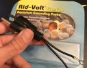
2) What do I do with the additional wire that is connected to the plug that has a metal plug connector? I have attached the image. It seems like I need to screw it somewhere. Shall I just put some isolation tape over there or just leave it like that in the air?

IMG_1317.jpg
 
The extra wire is meant to be fastened where a wall plate screw secures on the electrical box.
It’s to provide “grounding” too.
For that purpose to be effective, the box has to be metal and be certain it’s continuous metal grounded. There are several ways to ground a line but the best and safest I believe, is the continuous ground all the way to the main panel. Some electrical outlets although have the three prong connection, doesn’t mean they are grounded; a simple circuit tester will let you know if they are properly grounded
Some electrical wiring although seem to be grounded, are not even if you see the ground, hot and neutral wires in place.
I have a simple tester you can borrow to check on your power outlets.
Could you elaborate on how a circuit tester works? Can this be done with a multi-meter? Also, any insights on whether plugging one of these into a GFCI outlet works? I brought all of these, but still don't really know if I'm using them right :)
 
Very simple tool.
Must state that anyone working with electrical current/s has to do so in a safe manner. The tester will let you see if the wiring is set correctly at the outlet box.
 

Basically, this unit makes sure the floating ground of your tank is equal to the earth ground of your house. My house has two large copper rods physically pounded into the ground. These "ground" the house electrical system and are what are connected to that 3rd prong.

I should add that the 3rd prong is intended to be the short to ground in case of a malfunctioning electrical unit, and the current will flow there instead of through a person.
 
Last edited:
The extra wire is meant to be fastened where a wall plate screw secures on the electrical box.
It’s to provide “grounding” too.
For that purpose to be effective, the box has to be metal and be certain it’s continuous metal grounded. There are several ways to ground a line but the best and safest I believe, is the continuous ground all the way to the main panel. Some electrical outlets although have the three prong connection, doesn’t mean they are grounded; a simple circuit tester will let you know if they are properly grounded
Some electrical wiring although seem to be grounded, are not even if you see the ground, hot and neutral wires in place.
I have a simple tester you can borrow to check on your power outlets.
Not sure if I know how to mesure :D But if you are in the area you are welcome to stop by and see the tank :D
 
Could you elaborate on how a circuit tester works? Can this be done with a multi-meter? Also, any insights on whether plugging one of these into a GFCI outlet works? I brought all of these, but still don't really know if I'm using them right :)
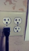
16248367416471922413414.jpg

These are two 20A circuits. Notice the T-neutral on the left; the breaker, smaller right slot must be the Hot/Line; bottom is the ground. The screws holding the wall-plate contact the metal box that has the EMC/metal pipe grounded all the way to the main panel (PG&E service)
The extra clamp on the Titanium Grounding Probe is a redundant grounding point. Some people in older homes, although the wiring is very old and has Line and Neutral wires only, newer plugs were installed that have the grounding point BUT no ground wire; that was done in the wrong manner; a two-prong receptacle has to be used or a GFCI can be placed since they are designed to detect the Ground Fault (or absence of it) and Interrupt the Circuit in milliseconds thus protecting you from electrocution.
The testers are designed to check on the circuit’s proper attachment of the wires. Bigger slot is the Neutral and in the newer plugs, the fastening screw is silver in color, the smaller slot normally has a gold colored screw for the Hot/Line; normally Black wire indicates the hot line but other colors are also used to ID separate circuits. Sometimes DIY-ers reverse these two wires; the tester will indicate a reverse polarity as it will show an open Ground, Hot, Neutral.
A multimeter can be used too, is a much more complete tool to test high and low voltages, amperage, resistance...
All you do is insert the probes and should give you a reading.
I’ve been to quite a few places where the hot and neutral are reversed or where the hot shorted somewhere. I’ve found the most difficult troubleshooting for me is a shorted neutral as they are also known as “common wire”
A friend for years had an extension cord running down to the garage from the kitchen; electricians told him he needed a re-wire of the whole basement and he left at least couple years pass by with that issue. I used both, multimeter and the simple tester; line was hot and the breaker at the box seemed to be in good working order after a visual inspection but still, no power. The circuit was open somewhere so to remove covers; nothing at any of the boxes...
I opened the breaker panel and noticed a neutral wire carbonized and the fastening screw fused to the neutral bonding bar, which prevented the circuit from completing at that point. Clipped the neutral and fastened in an available bonding post; that solved the problem.
The only way my friend tested for power, was to plug something or try to turn lights on; if he have had a simple tester, would have saved him at least a couple e years of running extension cords down to the garage.
Moral of the story is to get a simple wiring tester.
 
@Bolicks anything that you plug into a GFCI theoretically speaking, is protected but wiring it properly is key. There are newer AFCI Arc Fault Circuit Interrupters which detect an arc and shut-off in milliseconds as well.
 
View attachment 29103

These are two 20A circuits. Notice the T-neutral on the left; the breaker, smaller right slot must be the Hot/Line; bottom is the ground. The screws holding the wall-plate contact the metal box that has the EMC/metal pipe grounded all the way to the main panel (PG&E service)
The extra clamp on the Titanium Grounding Probe is a redundant grounding point. Some people in older homes, although the wiring is very old and has Line and Neutral wires only, newer plugs were installed that have the grounding point BUT no ground wire; that was done in the wrong manner; a two-prong receptacle has to be used or a GFCI can be placed since they are designed to detect the Ground Fault (or absence of it) and Interrupt the Circuit in milliseconds thus protecting you from electrocution.
The testers are designed to check on the circuit’s proper attachment of the wires. Bigger slot is the Neutral and in the newer plugs, the fastening screw is silver in color, the smaller slot normally has a gold colored screw for the Hot/Line; normally Black wire indicates the hot line but other colors are also used to ID separate circuits. Sometimes DIY-ers reverse these two wires; the tester will indicate a reverse polarity as it will show an open Ground, Hot, Neutral.
A multimeter can be used too, is a much more complete tool to test high and low voltages, amperage, resistance...
All you do is insert the probes and should give you a reading.
I’ve been to quite a few places where the hot and neutral are reversed or where the hot shorted somewhere. I’ve found the most difficult troubleshooting for me is a shorted neutral as they are also known as “common wire”
A friend for years had an extension cord running down to the garage from the kitchen; electricians told him he needed a re-wire of the whole basement and he left at least couple years pass by with that issue. I used both, multimeter and the simple tester; line was hot and the breaker at the box seemed to be in good working order after a visual inspection but still, no power. The circuit was open somewhere so to remove covers; nothing at any of the boxes...
I opened the breaker panel and noticed a neutral wire carbonized and the fastening screw fused to the neutral bonding bar, which prevented the circuit from completing at that point. Clipped the neutral and fastened in an available bonding post; that solved the problem.
The only way my friend tested for power, was to plug something or try to turn lights on; if he have had a simple tester, would have saved him at least a couple e years of running extension cords down to the garage.
Moral of the story is to get a simple wiring tester.
Thanks for the detailed explanation! I do have a multimeter on hand, so I'll give it a shot with that. I suppose I'll get a ~120VAC reading? Man, what a pain it must've been for your buddy...
 
AC, correct. You can plug one probe on the Hot and the other to the ground; if the ground is good, you’ll get a reading of 110/120v
Same if you test hot and neutral.
If you test neutral and ground, you should get no reading at all but sometimes shows some voltage as the neutral is a common wire. If you get an OL, means open line. In the event you get a 120 VAC reading from testing neutral and ground, that might indicate reversed polarity!
 
GFCI outlet is grounding correctly (it seems) - ground to hot is 120, neutral to ground is 0. On my extension cord/multi-outlet in the cabinet, I seem to get 120 from both neutral to ground and hot to ground - does this mean both are wired? Since both read 120 to ground, it should be safe to use as an outlet for the grounding plug? Thanks so much for your help on this!
 
1624856475802.jpeg
1624856475802.jpeg

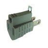
This is the correct adapter for electrical outlets that have only Hot and Neutral ports. Notice the Grounding Tab which is meant to be fastened via wall-plate screw and is only functional if the box is metal and is grounded. To test for ground on those type of outlets, stick one probe in the Hot and the other touch the screw; if grounded, should show 120VAC
 
View attachment 29117View attachment 29117

This is the correct adapter for electrical outlets that have only Hot and Neutral ports. Notice the Grounding Tab which is meant to be fastened via wall-plate screw and is only functional if the box is metal and is grounded. To test for ground on those type of outlets, stick one probe in the Hot and the other touch the screw; if grounded, should show 120VAC
Gotcha! Mine seems to be hot-hot-ground (if that's even possible haha). Basically, both of the slit holes, when touched to ground, read 120VAC
 
Remember working with live current presents a risk, HIGH risk but once finding the error in the wiring, switching power off is best.
 
Makes sense! I'm a little confused then - on my multi-plug both "slits", when connected to ground, read 120VAC - what does that mean?
Means wiring is correct.
Looking at the outlet with the ground port facing down, left big slot is the Neutral/white; the right port is the Hot.
 
Back
Top