got ethical husbandry?

Biocube 29, The Resurrection

My ATO is a mishmash of things. As it stands today, I'm using a Tunze Osmolator Universal for water level sensing. When the water level is low, the Osmo triggers a 12v automotive relay. This causes the relay to bridge 2 poles that are connected to my Apex break out box. When the Apex senses that switch port is "closed" it powers the PMUP on the 24v port on my EB832. Once the water level is reached, the Osmo kills voltage to the relay, the Apex switch port opens, and power is killed to the PMUP.
This rube goldberg machine can be greatly simplified if Neptune would release the optical level sensors they use in the DDR as a general purpose sensor.
ddr-eye-circle.png
 
My ATO is a mishmash of things. As it stands today, I'm using a Tunze Osmolator Universal for water level sensing. When the water level is low, the Osmo triggers a 12v automotive relay. This causes the relay to bridge 2 poles that are connected to my Apex break out box. When the Apex senses that switch port is "closed" it powers the PMUP on the 24v port on my EB832. Once the water level is reached, the Osmo kills voltage to the relay, the Apex switch port opens, and power is killed to the PMUP.
This rube goldberg machine can be greatly simplified if Neptune would release the optical level sensors they use in the DDR as a general purpose sensor.
ddr-eye-circle.png
Yeah, but then they'd rob you of your opportunity to be so ingenious.
 
I'm using the Avast ATO setup but it connects directly to the I/O port on the Apex bypassing the relay and breakout box.


Sent from my iPhone using Tapatalk
 
Today, I decided to up my water change game.

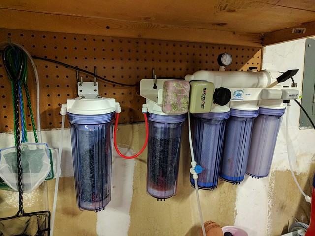
Step 1 was to add a 2nd RO/DI chamber to ensure absolute 0TDS.
31878435521_ef103e5e7a_z.jpg


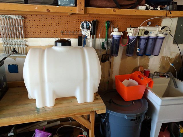
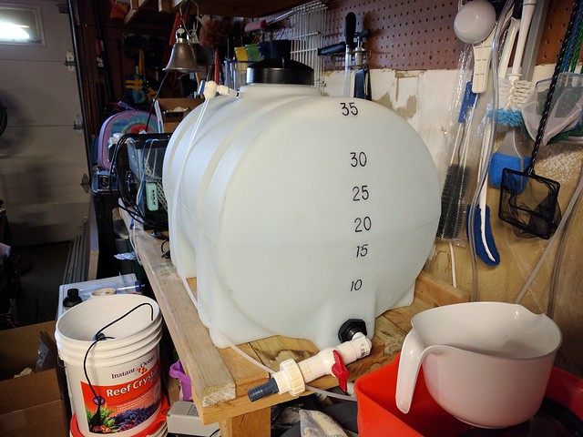
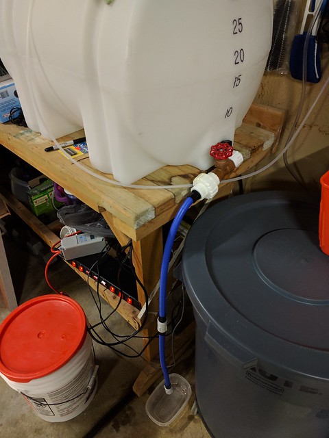
Step 2, install and plumb a new 35 gallon norwesco holding tank from Tractor Supply in Gilroy.
31185549873_b3f8f2dd9b_z.jpg


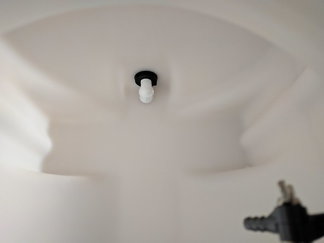
I added a 3/4" 90 degree threaded street elbow as a "pickup" tube so i can drain the tank to as close to bottom as possible.
31957674856_e6bdb5f0b5_z.jpg


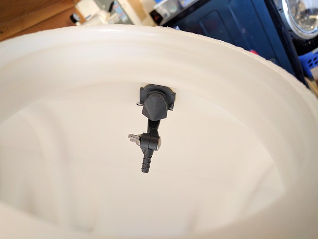
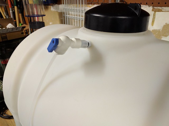
My float valve mounted near the neck of the main opening so I can make fine adjustments without dunking my arm in the tank.
31185551803_0831807d01_z.jpg


31995372405_4a65725923_z.jpg


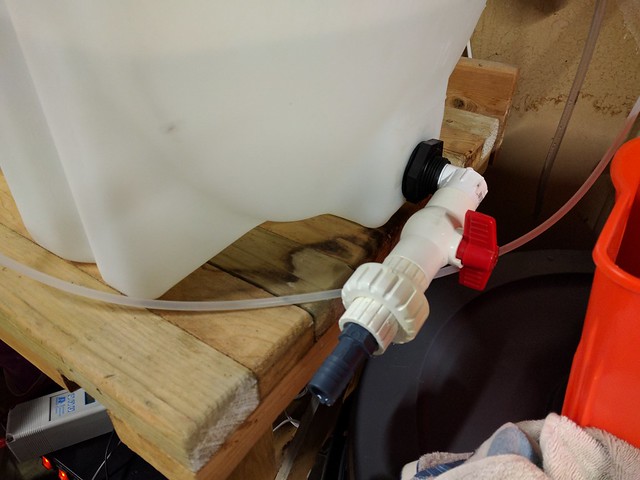
3/4" street elbow -> ball valve -> union -> barb. Still need to find some good flexible hose to finish it all up.
31154931814_c3689ce113_z.jpg
 
I like what you did with the drain and having the 90 degree fitting on the inside.

Tell me about the reasoning behind going to 3/4" for the float valve. I've just got my rodi going straight to the float switch with the 1/4" tubing.
 
Can I ask a question about your Biocube back section? I see you modified the middle chamber, but before that, did you have a LOUD water cascade in there? Just set up the same tank today (used), removed a huge amount of bioballs that were in the middle chamber and added water so it's between the Min/Max on the return chamber. It seems very loud in that middle chamber.
 
Can I ask a question about your Biocube back section? I see you modified the middle chamber, but before that, did you have a LOUD water cascade in there? Just set up the same tank today (used), removed a huge amount of bioballs that were in the middle chamber and added water so it's between the Min/Max on the return chamber. It seems very loud in that middle chamber.

I also bought mine used. It already had the bioballs removed. You can reduce the amount of noise by filling the rear chamber past the "Max" line. I have mine filled to about 3/4 full. I think the max line was to maintain a wet/dry filer with the bioballs. No longer needed with them pulled.
 
Last edited:
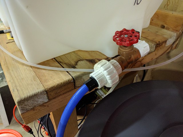
A few small updates to my RO/DI water setup. Swapped my ball valve for a stop valve. It gives me a little better control of the flow without the added height of a full gate valve.
31250762354_dd4c9ebe62_z.jpg


Decided to try a couple of flexable sprinkler hoses for my fill hose. I'm getting a few drips of a leak at the coupler in the middle. Not sure why. I may just switch back to a 3/4" barb and flexable bilge tubing.
31250775994_000afd47e1_z.jpg


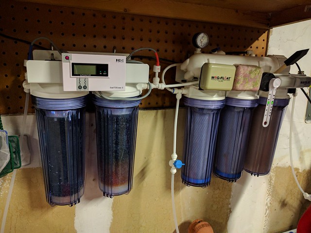
I re-plumbed my RO/DI setup to separate the RO from the DI section. The old setup used a 4 canister bracket with a single bracket add on. After bit of reading, I moved my pressure gauge between my stage 3 carbon block and my RO membrane input line. Not sure why it was not plumbed like this to begin with, but I bought the system a decade ago so who knows. Now the RO stages are on a more compact 3 canister bracket and my dual DI stages and new TDS meter are on a separate 2 canister bracket. Small changes, but I like the way it all turned out.
31435985194_3d9f190894_z.jpg
 
It's actually copper colored PVC. They had a white version but only in slip/slip. I wanted threaded, so opted for the off color. The only metal part is the screw that holds the handle on the valve shaft.
 
Last edited:
Back
Top