Cali Kid Corals

LED Q&A thread

For those who aren't going to be using PWM as a dimming option, you can replace the PWM circuit with a simpler voltage regulator circuit. You can then tap off this and power your cooling fan at 10V (maybe it will run the meanwell at less than 10...like 9 or even 8?) and cool only when your LEDs turn on.

If you are using PWM, you can run a parallel voltage reg circuit for the fans only. power it all up with an old laptop PSU or strong enough wallwart and all is well.
 
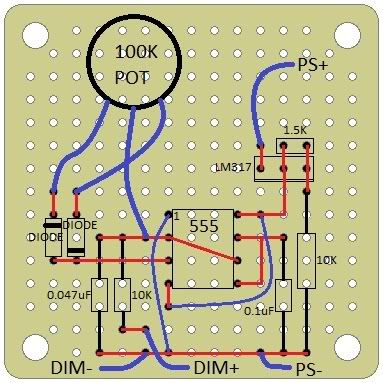
Omid (from meeting conversation), this is an EXAMPLE of how you can cheaply wire up the above schematic without printing/etching a PCB. The above plan assumes no etching, but rather a simple generic bread board available at Radioshack.

THESE DESIGNS ARE NOT MINE. Use at your own risk. I trust it works fine, but I haven't used it.


This is the final design Evil did.
Gomer said:
555PWM.jpg

Black lines are component leads
Red lines are bottom side solder traces
Blue lines are top side wires

Use a 12v or greater (up to 32v) power supply for this. A 12VDC wallwart should work perfectly fine for this. You hook the wallwart up to the +/- PS points


Hope this helps! If you have questions, feel free to ask

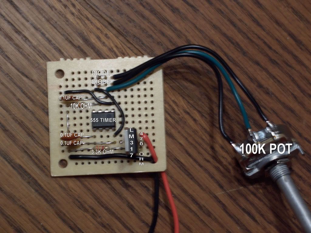
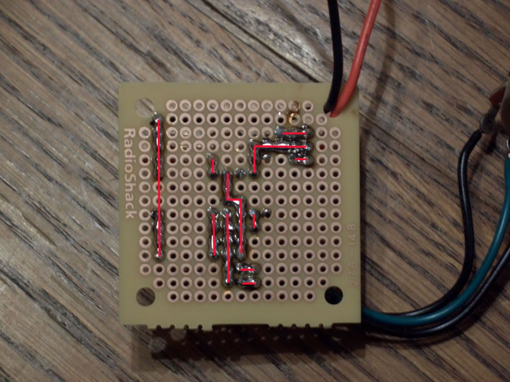
This is an assembled version of the old design (different from above).
It is to illustrate assembly.
PWMTOP.jpg

PWMBOTTOM.jpg
 
Question: How much of a heat sink would you need for a single emitter (ran at say 1A). I'm curious about setting these up more for a spot light feel more so than a panel that replaces a halide lamp.
 
mike, it really depends on the airflow and geometry. Since you are a numbers guy, I would do one of two things.
1) calculate it directly for a flat heatsink
2) calculate with a known airflow rate on a heatsink of a given specification.

Use this site for heatsink specs (pretty cool site)
http://www.aavidthermalloy.com/products/extrusion/northamerican_extrusions.shtml

Use this old whitepaper for thermal calculations (will need to apply cree specs, but the thermal resistance model holds)
Use these models
www.cree.com/Products/pdf/XLampThermalManagement.pdf
www.philipslumileds.com/pdfs/AB05.pdf
 
Hmm that's an interesting table/app, of course there's a handful ofmath on the Cree side of things to figure out how much thermal resistance you'll have.

Guess I forgot that by not doing a slab o' LEDs you really limit yourself to not being able to throw a fan on the back for additional heat removal, of course you could get all tricky with a conduit and mount your LEDs/Heatsinks into that and throw a fan on both ends...

Eh, I'll figure something out, I need to first figure out how to bring a light tube into the area/room first then I'll see how much bluing I'll need to do.
 
Yes u can.
Dimming in P version works just like D if you apply analog 0-10V.
The only difference is the ramp is just slightly off, but not noticeable.
 
thanks, Ill be attempting to build the 555 circuit today. Im going to be purchasing more of these drivers, should I opt for the D instead of the P now?
 
They both work the same way internally.
You can make a pwm signal work on the D or P and you can make a analog 0-10VDC work on D or P.
Analog works straight up on both versions. A simple potentiometer should do the trick.
PWM works on P and you would need to smooth the signal with a resitor/capacitor (RC network) so the signal turns analog for the D. The previous schematic should be a starting point for your PWM signal.
Or you can check this thread: http://www.bareefers.org/home/node/9211
 
access to your link is denied =( I was just going to hook up that 555 circuit to the dimmer leads on the 48p and that's as far in my research as I've gotten.
 
Yup you must be a BAR member to view that link :) $20 and it'll open right up for you :)
 
So Tony what's the light decay period of these Crees? I was reading a thread over on RC talking about the MaxSpect G2 LED pendant and it said the white LEDs (not Cree) decay by about 3% per 1000 hours. So they should in fact be replaced every 2-3 years to keep in an acceptable output range.
 
www.cree.com/Products/pdf/XLampXR-E_lumen_maintenance.pdf

acceptableout put is relative :p What is the % drop before MH get replaced?

Also, depending on drive level, you can just up the current to compensate.
 
Tony is my new google for all Cree specs :D "Tony how does...." (here's a data sheet)

Anyways yeah acceptable output is relative, I can't remember exact numbers I believe for halides they drop to but I think it's in the 75-80% range (there was an AA article on it or something), of course electronic ballasts dropped more than magnetic as magnetic ramped up energy output but color shifted more as a result I believe.

But my point was, that the big argument in favor of the LED setups is that yeah they have a more expensive initial cost, but if after 5 years they paid themselves off... well if you "need" to replace your LEDs at 3 years out because they dropped in intensity too much then you can't exactly use that 5 year period as rational argument to support the purchase of an LED setup... at least not without further analysis like replacement bulb cost (which is NEVER shown in LED vs MH cost analysis ... only for the MH bulbs does it add in a replacement cost)
 
Alright, I've dusted off a nano-cube (10g I think, one of those curved glass corner cubes) I'm going to use as a temp frag tank before/after swap (not that I really plan on coming home with much of anything :D). However I'm thinking of finally getting an aquarium upstairs, it's small it's compact, I can actually spend minimal time to make it look nice. So I'm thinking of using LEDs for a lighting source just to test it out the growing capacity, and to be honest it seems easier to get those into the hood than to shoehorn PC bulbs (that I really dislike using) in.

Was thinking of this DIY kit.
http://www.rapidled.com/servlet/the-35/12-Premium-LED-Do-dsh-It-dsh-Yourself/Detail

My question, would this be sufficient light? I'm thinking softies mostly because I don't want to deal with calcium/alkalinity and there won't be a skimmer on the tank. Is there anything there that is really not needed? Or is overkill? I know there's no heat sink to that price, but eh.. Hows the price? It seems kind of on target with pricing on individual LEDs ($6 or so), but what about the driver? Decent? Crap? Better ones are available? Lenses? Needed? Don't need? Might be nice? Foot print of the tank is roughly 14" x 14"

Also, what's the skinny on using a constant voltage source as opposed to current source? I know each one isn't perfectly to spec, but can't they be within a somewhat close spec that a variation of a 0.1V won't make a difference? Assume I don't run anywhere near 1 amp, maybe 700mA.


Also how thick are the LEDs? With a lens on them? With heat sink? I'm wondering if I might have to shoehorn them in anyways!
 
I think it's fine. Not the best, but hey, it's a complete package. If you buy bits and pieces, you are gonna save a few dollars, but you might spend more time trying to find stuff than you want to.
That driver won't go more than 700mA anyway. That's what the 700 means. And it is a non dimmable. Just FYI.
In my tank (Biocube 29) I'm using 24 LEDs and it's quite bright if I run it at 1A. So, I am at about 600mA right now.
I didn't feel the need of lenses since the LEDs stay quite close to the surface of the water. You might need lenses if you plan on elevating the heatsink instead of putting it on the hood. They wouldn't fit in my hood anyways with the heatsink I'm using.
I hope this helps.
 
Back
Top